=>Back To Characterization Lab
=>Down Load 2-d Data (.zip of a text file).
NIH Image is a free Mac Software that may be useful for Computer Program Project
(A free PC version called Scion Image for Windows, is available from Scion Corporation.
Password Name="computer" password="yoyo")
Computer Program
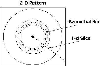
In many analytic measurements 2-dimensional CCD detectors have replaced step-scanner and 1-dimensional detectors. This is the case for IR/Raman spectroscopy, XRD, and SAXS for instance. Manipulation of large 2-d data sets, then becomes an important application of computer programming for analytic techniques. A typical manipulation of a large 2-d data set would be to azimuthally average a radially isotropic data set about a center point to produce the equivalent of a 1-d step scan. For example, in a powder-pattern for XRD, a diffractometer step-scans across 2
q generating an intensity versus 2q plot (Bold Dashed Line Below). Such a 1-d step scan might take 2 to 3 hours. If the diffraction pattern is isotropic, the same accuracy can be achieved in minutes using a 2-d detector. The 2-d pattern in this case is averaged about the beam center by binning the data into rings as shown below.
Cartoon of a 2-d pattern that would result by insertion of a 2-d detector perpendicular to the transmitted beam for a diffraction experiment. Solid circles are Debye-Scherrer lines, bold dashed line is data that would be collected from a step-scanner diffractometer, dashed circles delineate one of many "bins" that would be used to average a certain value of 2
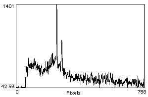
q, distance from the center. Dark spot in middle is the transmitted beam location.A large 2-d data set from a diffraction measurement on a semi-crystalline polymer will be provided as a "zip" compressed tab delimited text file. The file contains 1226 rows and 962 columns with integers that range from 22 to 1566. An image made form this 2-d table is given below with the slice indicated by the line in the following plot:
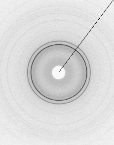
The Above two Images were made with the free software, NIH Image, that may be useful for this project,
Free Mac Software that may be useful for Computer Program Project
(A free PC version called Scion Image for Windows, is available from Scion Corporation.
Password Name="computer" password="yoyo")
Your computer program will perform the following sequence of operations on this 2-d tab delimited text file:
You should assume that the input data is in counts.
You can check your results for error by comparing your average intensity values divided by the square of the error which should equal N, the number of channels summed. This is if you correctly use I = sum(I)/N and err = sqrt(sum(I))/N. The error for an average intensity of about 50 is about ± 0.1 in my program. For the single channel slice the error for an intensity of 50 is the square root of 50, i.e. ±7.
Make sure your plots have REAL error bars on the data points. You can not put real error bars on a plot in excel and it is easy to tell the difference, i.e. you probably can't use excel to plot the results correctly. I'd suggest using Kaleidagraph or Sigma Plot for the results unless your program already makes the result plots. I think MatLab or Mathamatica can make scientific plots also.
The report must include: