=>Back To Characterization Lab
Download this page: =>Deformation Morphologies.pdf
3 Deformation Morphologies and Toughening of Polymer Systems.
Chapter 8 pp. 349
General Issues
We have considered in detail some of the semi-crystalline structures which are possible in polymeric systems. In general multi-phase morphologies in any engineering material are introduced to enhance physical properties. For a commodity polymer, such as polyethylene, the primary use will involve mechanical properties and crystallinity serves to increase the ductility (toughness) of this polymer.
The toughness of a material is enhanced by introduction of mechanisms for energy absorption in response to the application of stress. In polymers there are two main classes of energy absorption mechanisms which can be distinguished morphologically, crazing and shear banding. A primary area of interest to polymer morphologists has been the study of deformation morphologies with one aim to increase the energy absorbed when a polymeric material is stressed.
The design of polymeric materials with improved mechanical properties can lead to unusual results. For example, one might expect that the higher the degree of crystallinity in a polymer the higher the ductility. In fact this is not the case. There is an optimum degree of crystallinity where the maximum morphological deformation occurs, and correspondingly the maximum energy absorption. For high degrees of crystallinity failure occurs locally with little energy absorption. In order to understand this we need to take a careful look at energy absorption mechanisms and especially their morphological features.
This section also serves as a bridge between the two major areas of morphological study in polymers, crystallinity and phase behavior. In low molecular weight engineering materials there is basically no distinction between these two areas since materials such as metals are 100% crystalline, i.e. phase separation occurs between crystalline phases in most cases. In polymers phase separation between amorphous phases is the dominant topic, while formation of (usually a single) crystalline phase within one of these phases is more or less treated as an aside (with important mechanical consequences). Even in cases where two crystalline phases form such as in PVC toughened with chlorinated PE, or impact polypropylene and commercial PE blends (HDPE/LDPE/LLDPE) most morphological studies focus on liquid/liquid miscibility in the melt and post phase-separation crystallization. Crystalline/crystalline transitions in polymers are sometimes important consequences of deformation but occur rarely and are the realm of a small group of polymer crystallographers (mostly academic) such as Paul Phillips at U Tenn, H. Marand at VPI, A. Lovinger (formerly at ATT), E. Thomas (MIT formerly at UMass), R. Porter (UMass) etc. Some forms of Nylon are perhaps the most important of these polymers displaying crystal transitions although there is significant debate in all cases where attempts have been made to relate mechanical consequences to these transitions.
Observation of failure usually involve the micron-scale since the flaw size for normal use stresses usually occurs at close to 1 micron. In polymeric materials there are significant orientation effects which occur at sub-micron sizes which will be discussed.
Ductile versus Brittle Failure:
The morphological signatures of these two post-failure descriptions are fairly simple and correspond directly with your experience. Window Glass, Jell-O, neat polystyrene all show signatures of brittle failure which is described by a smooth, continuously curving sharp failure surface. Brittle failure is an indication that few energy absorption mechanisms have been involved.
In continuum mechanics, brittle failure is described by the Griffith criterion which describes the stress at failure in terms of a flaw size, c, the modulus, E and a surface term 2w (two surfaces are formed in failure). Equation 8.51 in Strobl, sc = (2Ew/(pc))1/2, and the stress intensification factor, KI = s(pc)1/2, as well as the critical stress intensification factor, KIc = (2wE)1/2, are used for brittle failure. Figure 8.31 shows that for a fixed rate of deformation, and temperature the Griffith approach is applicable to polymeric materials. The main issue is that "w" becomes a function of strain rate and temperature as will be discussed below.
Ductile failure shows a coarse, uneven failure surface, such as in clay, impact polystyrene, polyethylene. Ductile failure is an indication that significant energy absorption mechanisms were involved in deformation and in polymeric materials this is usually a good sign.
Crazes versus Shear Banding:
Polymeric materials which display ductile failure can be categorized according to the energy absorption mechanism involved. In some cases small cracks are seen normal to the applied stress. These small cracks if observed under the SEM or optical microscope are bridged by many tiny fibrils. The fibrils serve to stabilize these micron scale cracks. Such energy absorption is seen in polystyrene and impact polystyrene among other polymers. These tiny cracks bridged by fibrils are called crazes. Crazes typically give the polymer a white color after multiple bends. This white color is caused by light scattering from the fibrils. Crazes are shown in figure 8.3 on pp. 351 of Strobl.
In other cases polymeric materials do not display stress whitening. If these materials such as polycarbonate are observed under crossed polarizers lines of high orientation are observed at 45° to the direction of stress creating a cross-hatched pattern. Shear bands in polycarbonate are shown in figure 8.2 on pp. 350 of Strobl.
Typically, materials which shear band display a yield point and a plateau region where the work of deformation is consumed in forming more shear bands. Crazing is not associated with a yield point in general. The main difference, analytically, between crazing and shear banding is that crazing involves an increase in volume of the sample while shear banding does not. This means that crazing can only occur under conditions of dilatometric stress (stress where there is a force component which leads to an increase in volume) while shear banding can occur under any stress condition. A dramatic example of this is polystyrene which is the prototypical crazing material. If polystyrene is subjected to a compressive stress shear bands occur rather than crazes.
Neck Formation:
Figure 8.1 shows a schematic of neck formation in a shear banding sample such as polyethylene. The stress/strain curve displays a Hookean modulus followed by yielding behavior (a peak) and a plateau region where the stress remains constant with strain followed by an increase in stress at high elongation where terminal failure of the sample occurs. The yield point and plateau correspond with major, local morphological changes in the sample. If the sample is examined during this process it is clear that necking produces three zones in the sample, the neck, which is not elongated, the undeformed sample, and the necking front. Crazing is usually more homogeneous in the sample and does not usually lead to formation of a neck.
Initiation of a neck requires a critical stress, the yield stress. The neck will begin to form in a region of stress concentration or in a region where there are fewer molecular entanglements. The principle axis of stress occur at 45 degrees to the tensile load to these are the planes with the maximum stress in the sample. A combination of local inhomogeneity and inherent stress concentration along certain planes in the sample lead to dramatic local orientation of the polymer chains in an amorphous polymer such as polycarbonate, and dramatic local deformation of the spherulites and lamellae in a semi-crystalline sample. Both processes involve an initial energy barrier which leads to the yield point. The easiest example to understand, and the most relevant to morphology, is the yield point for a semi-crystalline polymer.
Mechanical deformation effects morphology from the largest scale to the smallest for a number of reasons. The manifestation of this for a semicrystalline polymer in spherulitic structure is that the spherulites are first destroyed as shown in figure 8.15 on pp. 363. For a sample which is necking this process occurs in a localized region of the sample in the yielding zone. Once the spherulites are destroyed and transformed in to a fibrillar morphology, further deformation can occur by destruction of lamellar morphologies which requires more stress and leads to the final up-turn in the stress strain curve before terminal failure of the sample. This process leads to disorganized lamellar structures. Such disorganized structures will rearrange into a more ordered lamellar structure on annealing (Strobl pp. 365 and 366 figures 8.18 and 8.19).
Crystalline orientation mimics to some extent this deformation driven orientation as shown in the 2-d XRD patterns of Strobl figure 8.17, pp. 364. Also, orientation of lamellae can be demonstrated in some samples such as that of figure 8.18 pp. 365 Strobl.
Strobl makes an important point in discussing figure 8.11 on pp. 360. All deformation morphologies of polymers show some type of relaxation on annealing. This includes shear banded structures but is most obvious in crazes which can "heal" at room temperature due to a kind of annealing effect. The implication is that deformed polymers have a "memory" which is a strongly distinguishing feature of these materials. A memory of the undeformed state is strong evidence that polymeric materials exist as a network even for solid state glassy or crystalline polymers which do not have crosslinked chains. The source of this network structure is entanglements. Therefore, the state of entanglements in a sample is a critical features which governs their morphological response to mechanical stress.
Ultra-Orientation:
Keller and Lemstra (figure 8.12 of Strobl) have taken this description of polymers a next step in developing "ultra-oriented" polymers through suppression of entanglements. ICI developed the process discovered by Keller and Lemstra into commercial product lines of ultra oriented polyethylene. The idea is that entanglements ultimately limit the degree of orientation possible for a polymer chain. Polymers, such as PE, can be brought to a state of low entanglement density by introducing a low molecular weight solvent. If such solutions or gels are rapid dried or if processing of the gel can be carried out, i.e. gel drawing, fibers of extremely high chain orientation can be produced (extended chain crystals). The strength of these fibers approaches the theoretical strength of a covalent bond. Covalent bonds are the strongest chemical bonds which occur in nature, i.e. much stronger than metallic or ionic bonds found in metals and ceramics. This means that the strongest material which could be made would be one of pure covalent bonds in perfect orientation (diamond is covalently bonded). Ultra-oriented PE only reaches about 70% of the ultimate modulus for covalent bonds and can be used to make bullet proof vests for instance. This is essentially the same material which is used to make milk jugs!
Distorted crystalline morphologies from solution spinning have been know for some time and include "Shish Kebab" morphologies and other distorted/fibrillar morphologies which have limited commercial significance.
Herman's Orientation Function:
The most common morphological measure of orientation is the Herman's orientation function, Strobl pp. 361 equation 8.17. Sor will take values from -0.5 to 1, when Sor is 0 the sample is unoriented, 1 means perfect orientation in the direction you have defined as a base, i.e. machine direction, and -0.5 means perfect normal orientation, i.e. transverse direction orientation. Typically, the orientation function is calculated for a diffraction peak where a 2-d XRD pattern is obtained and data at a specific (hkl) peak is collected as a function of azimuthal angle, Y. Ihkl versus Y can be plotted and for an oriented sample will show two humps, Y goes from 0 (MD) to 360°. Orientation in diffraction is at 90° from the hkl plane's orientation. You can think of this as a manifestation of reflection, i.e. there is no reflection from a mirror in the lateral direction.
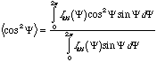
Ihkl versus Y data can be used to calculate <cos2 Y> for the Herman's orientation function through the integral,
For no orientation <cos2 Y> is 1/3, for perfect orientation <cos2 Y> is 1 and for perfect normal orientation <cos2 Y> = 0. The Herman's Orientation Function is calculated from,
![]()
yielding the values 0, 1, -0.5 for the three limits of orientation.
The geometric relationship between a crystal plane, hkl, and the unit cell axis is usually known and the orientation function from three peaks can be used to determine the orientation of the three unit cell axis with respect to the sample geometry through a coordinate system transform. For an orthogonal unit cell (axis at right angles), fa + fb + fc =1 and only two of the cell axis orientations needs to be determined, (lattice orientation can be determined from two peaks). The orientation function is usually, linearly related to some physical properties such as modulus.
Strobl discussed the measurement of orientation by two other techniques, optical birefringence (difference in the index in different sample directions) and using NMR (a complicated procedure for specialists). Orientation varies with size scale of observation for materials which display multiple levels of structure through the relationship between different levels of structure, i.e. crystalline lattice => lamellar orientation => spherulitic orientation => bulk orientation. The arrows are not necessarily linear transforms since there may be some degree of disorganization of crystalline lattices in a lamellae, for instance, or the lamellae may be better oriented in spherulites than the crystal lattice.
Orientation is a critical feature of polymers since most processed polymeric materials display high degrees of orientation which directly impact the physical properties.
Crazing:
Crazes are micron-scale cracks which are bridged by filaments of polymer. Crazes are oriented 90° to the applied stress.
Strobl mentions on pp. 373 figure 8.25, and the associated discussion, that the mechanism for fibrillar growth in a craze is basically similar to the mechanism of shear banding. There is strong evidence to support this model. Crazing does not occur below 2*Mentanglement, bulk stress strain curves match micro-fibril data as shown in figure 8.25, crazing is a time dependent phenomena, i.e. there is a fixed time associated with the formation of crazes which changes with temperature and the presence of solvents meaning the process is viscoelastic in nature.
Shear banding is the basis of crazing if combined with some mechanism for cavitation. That is, crazes form in a two step process, cavitation followed by necking of micro-fibrils. The standard description of the cavitation process, discussed on pp. 373, figure 8.26, is that of Argon. Argon's model is based on pressure driven flow at the craze tip. A pressure gradient develops due to dilatational stress which is concentrated by the flaw. The region which is under highest dilatational stress is unstable to the advancement of a meniscus towards the craze tip. The unstable region decays into voids and stable connecting gaps which, after necking is initiated, form fibrils which bridge the craze gap. The failure surface in figure 8.34 shows the result of this process.
Evidence for Time Dependence:
Figure 8.22 demonstrates that there is a time constant associated with the formation of crazes (plot of number of crazes as a function of time of application of stress). This curve reflects an exponential growth of the form Number = C exp(-t2/t2), where t is a time constant for craze growth, t = f(T).
Evidence for Dilatational Effect:
Figure 8.23 demonstrates that crazing only occurs in the presence of dilatational stress. The stress is applied horizontally in figure 8.23. The presence of the hole relieves dilatational stress on a line which passes horizontally through the hole. Dilatational stress is enhanced vertically on a line through the hole. Crazes only appear along this dilatational line!
Continuum (Griffith) Analysis of Crazing:
In figure 8.31 Strobl shows the result of visco-elasticity on the Griffith approach mentioned above. As was noted above, the Griffith approach works for polymers but only at a fixed temperature and rate of strain. For a traditional brittle material, such as silica glass, there is only a single value for crack propagation, dc/dt, which is displayed above a critical value for KI, KIc = 2wE. Beyond KIc crack growth progresses in a catastrophic, unstable manner.
For polymers a stable growth rate occurs which is a manifestation of crack stabilization through the necking behavior of fibrils derived from meniscus instability at the craze tip. GIi reflects the initiation of crazing and the plateau just before GIc is the stable growth plateau where fibrillar necking occurs. Above GIc crack propagation is unstable and the sample fails catastrophically.
Morphological Manipulation of Energy Absorption Mechanisms:
Figure 8.27 shows that the presence of small domains can lead to enhancement of energy absorption mechanisms in polymers. This is true both for crazing and shear banding as evidenced by the predominance of shear banding in semi-crystalline polymers. It is the use of multiphase materials for mechanical enhancement in polymers which is the premise of most development of morphologies. This is equally true of semi-crystalline and phase separated structures. Often, the development of such morphologies has progressed either in an Edisonian or in a serendipitous way. The development of high-impact polystyrene (figure 8.27) and development of most commercial semicrystalline polymer morphologies have certainly followed this motif. More recent manipulations of morphology, particularly in block copolymer systems (SBR rubber in tires for instance) are an exception to this approach and the future of mechanical improvement, as well as understanding complex systems which exist, are based on a more scientific approach. This scientific approach to the development of multiphase morphologies from partially miscible systems represents the second major area of polymer morphology (after semi-crystalline morphologies), and will be the topic of the next section we will cover.
The mechanism for enhancement of crazing has been debated in the literature and one can see why if one compares the effects of the hole in figure 8.23 and the elastomer domains in figure 8.27. Both holes and elastomeric domains serve to modify the stress distribution leading to enhancement of dilatational stresses and crazing. In addition to the physical presence of "void" like holes, the elastomer in figure 8.27 may modify the modulus of the matrix polymer through partial miscibility and serve to elastomerically bridge the hole. Elastic deformation of the disperse phase might be an additional mechanism for energy absorption in such two phase materials. The minority component in such a composite is usually more expensive than the majority phase, so the volume fraction of minority phase is usually minimized for optimum performance.
There are several mechanisms to produce a two phase material and from a historical perspective, the development of HIPS (figure 8.27) should be considered in some detail both as an indication of an Edisonian approach which worked as well as suggesting some of the complexities of polymeric systems.
Polystyrene and polybutadiene are two of the least expensive commercial polymers and it was long sought (circa 1960's to 1970's) to "blend" the two materials as an alloy (single phase). The mechanical properties of the two polymers are highly complementary, styrene being a brittle, high modulus glass at room temperature and butadiene being commonly crosslinked into an elastomer for tire applications. Mechanical mixing of PS and PBD lead to poor results with a cheese like material resulting due to immiscibility. It was known that PBD was soluble in toluene and benzene as well as monomeric styrene which is related to these aromatics.
It was thought that by swelling PBD in styrene monomer followed by polymerization of the styrene to PS some compatibility between the phases might results, however this also lead to poor materials (GE and Dow circa 1967). The process for production of HIPS was developed at GE basically by an Edisonian approach (try anything). In the process a critical amount of extremely vigorous mechanical mixing is necessary to enhance the volume fraction of PBD domains through incorporation of PS micro-domains in the PBD phase (see figure 8.27) The combination of a low volume fraction PBD and incorporation of PS in the PBD domains to boost the volume fraction of the disperse phase is thought to lead to the amplification of crazing and dramatic toughness of HIPS. The process of polymerization of styrene swollen PBD results in a "phase inversion" where the majority swollen PBD phase becomes a minority phase a polymerization proceeds.
The production of tough polymers through reversible phase separation of miscible polymers was though to be an are of high potential for controlled production of tough materials. Only in the block copolymer systems has this dream reached fruition, however, much knowledge concerning the phase behavior of polymer/polymer systems has been learned which is critical to understanding polymer morphologies.
=>Back To Characterization Lab
Download this page: =>Deformation Morphologies.pdf