Model for Vertical Cast Film
![]()
The purpose of this section is to describe the vertical cast film process and model the effects of operating conditions and polymer characteristics on the fabrication of the film.
Numerous references have been published that have modeled the cast film process. For this exercise, we will model the cast film process with the following arrangement:
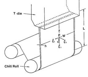
image: Kanai, T., Campbell, G. A., Film Processing, 1st edition, Hanser Gardner Publications, 1999.
Where x1, x2, x3 are the cartesian coordinates in the machine, transverse, and normal directions, w is the width of the film in the transverse direction, h is the thickness of the film in the normal direction, v is the velocity of the film in the machine direction, and z is the distance from the die at an arbitrary point, P.
Tensors at P
The strain rate tensor, d, is given by:

Where dii is the component of the strain rate tensor in the ith normal direction and is given by:
![]()
Where x is the distance (w or h) in the specified normal. In addition, the sum of the components of the strain tensor must equal zero. The strain tensor then becomes:

Next, we define the stress tensor, s, as:

In terms of the defined problem, the stress tensor is given by:

Where: h is the shear viscosity and is given by:

E is the activation energy, R is the gas constant, n is material constant of power law fluid, and ho is the shear viscosity at P=2 and T=T0.
P is the second invariant of the strain rate tensor and is defined by:
![]()
Energy balance about point P:
The force about point P is the sum of the tension applied to the film, FL, and the gravitation forces and is equal to the product of the machine direction component of the stress tensor and the cross sectional area of the film. This relationship is given by:
![]()
The heat balance about point P is simply the heat content of the polymer with respect to changes in temperature relative to position in the gap (i.e. dT/dz). This change in value is equal to the heat lost to convection and radiation. This relationship is given by:
![]()
Where CP is the specific heat of the polymer melt, T is the melt temperature, Tair is the ambient air’s temperature around the molten curtain, e is the emissivity, l is the Stefan-Boltzman constant, and U is the heat transfer coefficient obtained from the following equation:

Where Kair is the thermal conductivity of air, rair is the density of air, L is the gap between the die and the chill roll, vave is the mean velocity through the gap, and Cair is the specific heat of the air.
A more complicated model would incorporate changes in specific heat and emissivity with the change in the melt’s temperature.
The following figure (from Kanai: Film Processing) shows the changes in the velocity in the machine direction (v), film thickness (H), and temperature (T) relative to position in the gap. Position Z = 0 is indicative of the exit of the die.
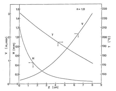
Kanai, T., Campbell, G. A., Film Processing, 1st edition, Hanser Gardner Publications, 1999.
The film velocity increases exponentially as it moves further away from the die, causing the thickness of the film to rapidly decrease.
The following figure shows the relationship between the machine direction components of the strain rate tensor (d11) and stress tensor (s11).
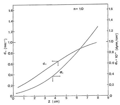
Kanai, T., Campbell, G. A., Film Processing, 1st edition, Hanser Gardner Publications, 1999.
From this figure, it can be seen that the magnitude strain rate increases, then plateaus as one progresses further away from the die. The stress increases exponentially because of the increase in the strain rate and the viscosity.