Introduction:
What are x-rays?
X-rays are short wavelength electro-magnetic waves. (electromagnetic spectrum link)
1) We have all seen electro-magnets which are made of a coil of wire and which display a magnetic field when electricity flows through the coil. This magnetic field is described by one of Maxwell's laws know as the generalized Ampere Law:
Line integral
Here a changing electric field associated with current is related to an associated magnetic field. The direction of the magnetic field is perpendicular to the direction of the electric field. For a sinusoidally oscillating electric field the magnetic field is out of phase by 90°, i.e. the magnetic field reaches a maximum when the electric field reaches a minimum.
2) Electrical generators involve the motion of a magnet on a shaft which creates an electric field and current in a surrounding coil by Faraday's law:
Line integral
![]()
A changing magnetic field is associated with the creation of an electric field. The electric field is perpendicular to the magnetic field and is out of phase by 90°.
3) Any disturbance in electo/magnetic space can create an electro-magnetic wave just as a physical disturbance in a pool of water can create a mechanical wave where kinetic and potential energies are converted. A wave in a pool of water has an associated energy which is stored in the oscillation between kinetic and potential energies. Similarly, an electromagnetic wave has an associated energy. Some typical disturbances in order of increasing energy are: oscillating charge in an antenna (radiowave), current flow through a tightly coiled, thin wire (light/heat), change in momentum of a charged particle at high velocity (x-rays).
Features of Electromagnetic Waves:
1) EM waves are described using a sin function of time and space. That is, at a fixed time the wave varies in Amplitude, A, with spatial position and for a given position in space the wave varies in amplitude with time.
E = A sin[2px/l -2pnt]
B = B0 cos[2px/l -2pnt] Out of phase with E by 90°
E and A have direction. l is the wavelength, n is the frequency.
2) The frequency and wavelength are related by the velocity of the EM wave which in vacuum is c, "the speed of light".
l = c/n
c = 3 x 10⁸
m/s3) The amplitude is related to the "intensity" of the EM radiation:
Intensity = |A|2
Intensity doesn't have direction
4) The energy of EM radiation is directly related to the energy associated with phenomena by which it is made and is not associated with the intensity. Planck's law states:
Energy/photon = hn = hc/l
h = 6.63x10⁻³⁴ J s
The idea that EM radiation has an energy is tied to the particle view of EM radiation, i.e. there is a particle called a photon which has no mass which carries the EM energy and has momentum, p.
p = hn/c
(you can obtain this from E = mc2 = hn and p = mc)
5) X-rays and other EM radiations are generally composed of a number of photons so one can consider the relationship between different waves in a beam. If all waves in a beam are in-phase, that is have the same phase angle (peaks of waves coincide in space) they are called coherent. Waves which are not coherent can interfere with each other leading to a reduction of the intensity.
When considering interference of two waves one adds or subtracts amplitudes of the electric field vector E. The intensity which is measured is the square of the resulting amplitude, #3.
A beams with waves which are all progressing in the same direction are termed a well collimated beam. Collimation refers to the divergence of the waves in a beam. A light bulb produces uncollimated light which spreads in all directions. The sun's rays, when they reach earth are well collimated since the angular divergence is low.
6) If all waves have the same frequency (or wavelength by #2) they are called monochromatic (one color). A source like a light bulb or x-ray tube generates polychromatic (white light) radiation (many wavelengths) and a source like a laser or a synchrotron yields monochromatic radiation.
The polychromacity of EM radiation is tied to the mechanism of formation. If the formation event is specific in terms of the energy transfer associated with the formation event, monochromatic radiation results. If the formation event is statistical (distributed in energy) polychromatic radiation results.
7) EM radiation can always be assumed to travel in a straight line.
8) EM radiation interacts with matter in different ways depending on the energy associated with a photon. That is, energy decides what happens while intensity decides how much happens. Radio waves are low energy/high wavelength (see figure 1.1) and can pass through most materials with no effect. IR vibrates bonds and can generate heat. Light changes the polarization of molecules which is a minor effect. UV can dissociate weak bonds and cause degradation. X-rays are a type of ionizing radiation that can ionize atoms and molecules. Typically, x-rays have wavelengths on the Ångstrom scale. Generally, the lower the wavelength of radiation the higher the danger due to the higher energy associated with short wavelengths see #4. It is also more difficult to produce and use high-energy photons since they must result from an associated high energy event and they are absorbed by most materials through the interactions mentioned above.
9) Some differences between x-rays and light:
i) x-rays don't refract because the equivalent of the index of refraction for x-rays is extremely close to 1 for all materials. There are no x-ray lenses and no x-ray microscopes.
ii) x-rays can reflect off smooth surfaces but only at very shallow angles (<1°) due to the closeness of the index of refraction to 1.
iii) x-rays are absorbed by heavy atoms (atoms with many electrons) but can pass through low molar mass atoms to a significant extent. This is why they are useful for medical x-ray images.
Bragg's Law:
1) We will later derive Bragg's law which describes the angular relationship for constructive interference of monochromatic EM waves diffracted by a regularly arranged structure with a preferred separation distance, d.
For an incident EM wave of monochromatic wavelength,
l, coherent waves are produced at an angle 2q from the incident direction if the diffracting material has domains which interact with the radiation and are spaced at a distance d, l/2 1/sinqBragg's law is used to determine the spacing d. The smallest spacing observable with a radiation of wavelength
l is l/2. Spacings larger than this are observable at angles less than 2q = 180°. The term 1/sinq serves as an amplification factor.2
q = 180° is in the direction of the incident beam.2) The reason to introduce Bragg's law at this point is to note that there are two requirements for an x-ray diffraction camera which are directly implied by #1. First, a mono-chromatic source is needed to obtain good values of d (
l should be single valued). Secondly, a camera will need good angular resolution (good collimation) to obtain good values of d (q should be single valued). The next part of this course will deal with the production of mono-chromatic x-rays using an x-ray tube and attenuators or other monochromators.Production of X-rays:
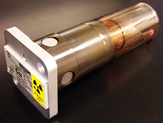
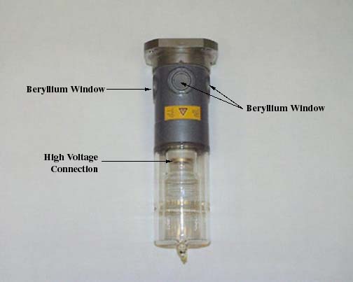

a) Phillips analytic x-ray tube, b) another view of tube, c) European Synchrotron Research Facility
Since x-rays are high energy EM waves, a high-energy event is needed to produce them. Generally they are produced by a change in momentum of a charged particle, typically an electron. This can be achieved in a number of ways, 1) driving electrons down a high voltage drop in a vacuum tube into a metal target which essentially stops their linear velocity. 2) In a vacuum, accelerating electrons or protons (or positrons) with high voltage and suddenly changing their path using magnets (a synchrotron such as APS in Chicago) 3) Changing the direction of electrons in a conductor under high voltage, x-rays are produced by high voltage transformers. 4) Decelerating electrons in a video display or TV, color TV's and video generate x-rays. 5) high-energy events such as nuclear explosions and cosmic events produce high intensity x-rays and cosmic rays (lower wavelength than x-rays).
In this course we will only consider lab sources for analytic x-rays although the largest source of background radiation in a typical x-ray lab comes from the high-voltage transformer.
Figure 1-15 in the book shows the cross-section of an x-ray tube.
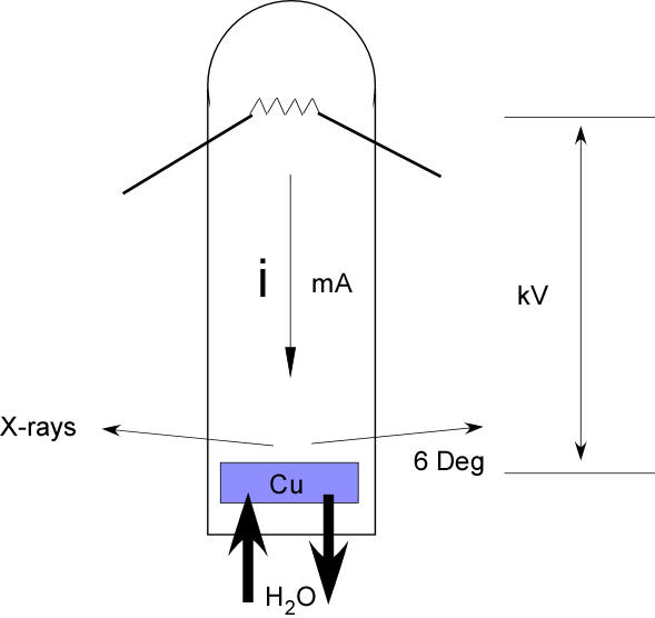
The components of a tube generator are a filament which serves as a source of electrons and which generates a tube current, i, flowing from the cathode (filament) to the anode, a high voltage drop, V, between the filament and an anode composed of a metal such as copper. A high vacuum to allow for free transport of electrons (electrons are quickly absorbed even by gas atoms). X-ray transparent windows, usually made of beryllium (a toxic metal). A cooling system to dissipate the large amounts of heat which are generated when electrons collide with the anode.
The main limitation to the flux or intensity of x-rays that can be generated by a tube source is the heat generated in the process. More than enough heat is generated to melt the anode and destroy the tube. High flux generators use a rotating anode which dissipates the local heating of the anode over a cylinder of target metal and can operate at much higher power than a fixed anode generator.
1) Since Bragg's law is interested in the wavelength of the x-rays and since Planck's law tells us that the wavelength is tied to the energy of the radiation we can consider the highest energy which could be dissipated as x-rays in the tube generator. The source of energy is the kinetic energy which is contained in the electron as it passes from the filament to the anode,
KE = eV = the maximum amount of energy which could lead to an x-ray.
This will be the limiting energy for an x-ray and since small wavelengths have higher energy this corresponds to the smallest wavelength which could be produced,
lswl,l
swl = hc/KE = hc/eV = 12,400 / Vwith V in volts and l in Ångstrom.
2) You can think of an electron hitting copper as a ball being randomly thrown into a forest. Some fraction of the time the ball will hit a tree head on and will result in lswl. Most of the time the ball will graze off a tree and hit another tree before coming to rest. A distribution of energy of collisions is expected from such a statistical event which leads to a distribution of wavelengths. This is called Bremsstralung radiation after the German word which means breaking and German for radiation. This is also called white radiation reflecting the polychromacity of the radiation (i.e. white light = polychromatic light) and the continuous spectrum since there are no sharp (discontinuous) features in the I versus l plot.
3) The total number of photons produced by the tube generator in such events is proportional to the number of electrons in the anode atoms, Z (atomic number), the number of electrons being accelerated (the tube current i) which is related to the filament current, and to the voltage drop in the tube, V, raised to some power which reflects the statistical nature of the event, V2:
The Characteristic Spectrum:
The x-ray tube has two control knobs, the tube current, i, and the voltage drop, V. Increasing either will increase the heat generated in the tube so there are limits to how much energy (kilowatts) can be input into the tube. The power (in kilowatts) is the voltage in (kilovolts) times the current (in milliamps) divided by 1000. A generator operating at 40kV and 100mA is operating at 4kW which is typical for a 12kw rated rotating anode generator. Fixed anode generators operate at similar voltages and lower currents. The reason for this is shown in the dependence of the x-ray spectrum (Intensity versus wavelength) as a function of voltage drop, figure 1-4 pp. 7.
As voltage is increased high intensity spikes which are characteristic of the target metal appear. These spikes in intensity are extremely narrow in wavelength and it can be inferred that the event from which they arise has a narrow energy span. Because both the voltage at which these lines appear and the wavelength at which they occur are characteristic of the metal in the target they are called the Characteristic lines or characteristic spectrum.
The appearance of characteristic lines can be explained in terms of atomic orbital theory. Electrons in an atom exist in discrete (fixed) energy levels according to quantum theory. These orbitals are labeled K, L, M in order of increasing energy. An electron that has more energy than the orbital energy (Vcritical) can remove an electron from it's orbital. This is most likely for the K orbital since it is of the lowest energy. When a low energy orbital is made vacant by such an ionization event, electrons from the higher energy levels fall to the lower, i.e. L to K or M to K. Because the orbitals have fixed energies, the difference in energies between orbitals is of fixed value, leading to a high intensity monochromatic band. L to K yields a different energy than M to K so several of these sharp bands can be produced. The lower energy L to K (Ka-radiation) transition is more probable and is more intense than the higher energy M to K transition (Kb-radiation). Higher energy for the Kb radiation means it occurs at a lower-wavelength.
1) The intensity (how many photons) of a K line is proportional to the tube current, i, and the difference between the tube voltage and the critical voltage for K excitation raised to about 3/2 power.
IK line = B i (V-VK)1.5
2) The wavelength of a characteristic line follows Mosley's Law,
where C and
s are constants and Z is the atomic number (table of x-ray energies). This is close to a Z2 (square of number of atomic electrons) dependence of energy (hn) which might be expected by a process involving two electrons, one ejected and one decaying to a lower energy level.3) The K excitation energy is equal to the K orbital binding energy, WK
. The voltage for appearance of characteristic radiation for Copper is 9kV, for Mo it is 20kV. Characteristic lines will appear at voltages higher than these at any tube current. This means there is a minimum V to operate the tube generator but no minimum i.4) The intensity of Kb is always smaller than Ka (typically 5 times smaller) because it is 5 times less likely that the high energy event, Kb, will occur.
5) CuKa has a wavelength 1.54Å, CuKb 1.4Å
MoKa has a wavelength 0.71Å and MoKb 0.63Å
These are the two most common targets and in both cases the alpha radiation is usually used in an XRD experiment and the beta radiation must be removed by attenuation (or filtering) or by monochromatization using crystals.
6) Depending on the tube operating conditions the characteristic lines are typically 50 to 100 times as intense as the Bremstralung radiation.
7) The characteristic lines offer a high intensity essentially monochromatic (Dl = 0.001Å). The b radiation must be removed since this is the primary source of polychromacity.
Absorption:
The b radiation must be removed to use Bragg's Law. The simplest way to do this is to filter or attenuate the beam.
Attenuation:
For linear absorption, DI = -I m Dx, where m is the linear absorption coefficient and x is a linear distance through an absorbing material, I is the incident intensity and DI is the change in intensity. Since the amount of change depends on the incident intensity, I, and because I changes for each differential element of the absorber, i.e. as the beam passes through the absorber the intensity decays this equation leads to an exponential decay on integration across the sample,
this equation yields ln(I/I0) = - m x, which can be written, I/I0 = exp(-m x).
The latter is the Beer-Lambert Law for absorption which is used for all linear absorption experiments such as IR spectroscopy etc.
The absorption of x-rays can be used as an analytic technique to precisely determine the composition of heavy atoms in a material or surface (XANES and NEXAFS (other link, yet another link).
Optimum Thickness for a Transmission experiment:
The amount diffracted is proportional to the path through the sample, x. The diffracted beam must also pass through the sample so Beer's law applies, Idiff = x exp(-m x).
The maximum in diffracted intensity for a transmission experiment occurs when dIdiff/dx = 0.
dIdiff/dx = exp(-m x) -x m exp(-m x) (= 0 at maximum diffracted intensity).
so xmax = 1/ m. For a transmission experiment the optimum transmitted beam intensity is exp(-1) or 37%. Transmission experiments are useful for polymer samples but are of little use for metals since 1/m is very small for metals. For polymers 1/m is about 2mm.
Absorption Edge
We already know that different wavelengths have different interactions with material, i.e. IR vibrates molecules (heat), visible light polarizes molecules, UV can break weak bonds, x-rays can ionize materials. These interactions are the source of absorption and since we already know that discrete (quantized) events can occur when electrons of sufficient energy interact with atoms, we expect some type of discrete behavior to occur when EM radiation of sufficient energy (low enough wavelength) interacts with atoms leading to discrete behavior of the absorption coefficient as wavelength is changed.
These discrete events (discontinuous behavior of m with l) are called absorption edges and correspond to photons of critical energy for an atomic orbital interacting with atoms. Thus, the absorption edges are labeled K edge, L edge, M edge. At an absorption edge there is a discontinuous increase in absorption as energy is increased (wavelength is lowered) which corresponds to a quantized mechanism of energy absorption occurring.
1) The wavelength of the absorption edge is defined in terms of the orbital energy so lK = hc/WK. Just below the edge in wavelength is the maximum absorption.
2) The increase in absorption coefficient at an absorption edge such as the K edge for nickel, Ni, can be very large (8 times for this case). This effect is amplified by Beer's law to a power of transmitted intensity, i.e. I/I0 goes to 1x10⁻⁸!! This means that the absorption edge can be used to discriminate close peaks in a spectrum such as the Cu Ka and Kb peaks, if the attenuator is carefully chosen.
3) Below an absorption edge, in wavelength, the absorption coefficient decays with wavelength according to m a l3. This observed phenomena is probably related to increased energy of the radiation being able to penetrate deeper through a material for a given mechanism of absorption (i.e. the absorption mechanism is constant between absorption edges.
Low wavelength x-rays are called Hard x-rays because they penetrate more easily.
High wavelength x-rays are called Soft x-rays for similar reason.
4) The absorption coefficient is a function of the number of electrons in an atom since it is electrons which interact with x-rays, m = k r l3 Z3. where k is a constant, Z is the atomic number and r is the density.
5) If an attenuator is chose one atomic number below the atomic number of the anode (or the closest you can get to this) the b radiation can be attenuated out almost completely. This sets up matched pairs of anode metal and attenuator metal the most common being Copper anode (Z=29) and Nickel attenuator (Z=28) and Mo anode (Z=42) and zirconium attenuator (Z=40), [Niobium (Nb) with Z=41 is very rare.]
6) In the x-ray absorption process an electron is emitted (photoelectron) which can lead to a decay of higher energy orbitals just as in the tube generator. This decay leads to emission of radiation from the attenuator called Fluorescent radiation. This is mostly a problem when Iron or Steel sample holders are used in an XRD camera which has a Copper target. Components of XRD cameras should not contain Iron if possible. A solution to this problem, i.e. if you are interested in steel, is to use Mo as an anode material.
7) The absorption spectrum for lead is shown in Fig. 1-10 on page 16. Due to the close spacing of the L I, II, III and M lines it is an excellent absorber for x-rays of greater than 0.6Å wavelength. This includes most of the radiation produced by a Cu or Mo target. Mo requires more lead than Cu due to the lower wavelengths involved.
Synchrotron Radiation: See Link
A synchrotron is generally a national user facility where engineers and researchers from companies, universities and national laboratories share a facility supported by the government or a consortium of governments such as the European Union. The purpose of an x-ray synchrotron such as ESRF in France, APS in Chicago, NSLS on Long Island NY, the SLAC in Palo Alto California is to provide x-rays and instrumentation for industry and universities where there is some advantage to a high flux (high intensity) x-ray source. Synchrotrons, for instance, are widely used by the pharmaceutical industry in the discovery and development of new drugs. The bioactivity of drugs can be predicted in many cases if the structure of the drug can be determined. Only small amounts of the drugs are initially produced and are crystallized into 50 to 100 micron size crystallites in some cases. Conventional x-ray sources can not produce an x-ray beam on such small size scales with sufficient flux to obtain a diffraction pattern or measurement of such a diffraction pattern might take many weeks. Drug companies are interested in screening hundreds of such materials, a task that is essentially impossible with conventional x-ray sources. Much of the work done at synchrotrons focuses on high resolution diffraction studies using CCD detectors with on the order of 10 micron size resolution. High resolution diffraction patterns are fed into supercomputers to determine 3D molecular models that can indicate the active site of new drug molecules. This field is often referred to as protein crystallography. (course on protein crystallography, links). Protein crystallography is just one of literally millions of measurements that can only be done using the high flux, polarization, collimation or pulsed time structure of synchrotron radiation. In metals, grazing incidence diffraction to investigate the crystallinity at the surface of processed parts or time studies of phase change on the millisecond scale. In polymers synchrotrons are used for in situ studies during processing, studies of polymers in solution and a wide variety of kinetics studies. In ceramics synchrotron radiation has been used to study nano-particle growth in dilute aerosol streams.
A synchrotron can produces high intensity x-rays by changing the momentum of charged particles (electrons, e-, ESRF, or positrons, e+, APS, the latter being a form of anti-matter). Charged particles are produced and accelerated in a linear accelerator called the insertion device (ID). The particles are then "injected" in "bunches" into the ring. The type of injection, single bunch, multiple bunch etc. determines the time signature of the x-ray signal on time scales of the ring diameter/the speed of light, typically micro-seconds. The momentum of the charged particles is changed by driving the particles at the speed of light through an evacuated loop composed of straight and curved segments. The particles are forced to turn corners by bending magnets (BM). Energy lost in traveling through the loop is added to the particles by a radio frequency (RF) cavity that energizes the particle beam. Along straight segments focusing magnets (FM) maintain the charged particle path and stabilize the ring current. Also along straight paths between bending magnets insertion devices produce high flux and narrow wavelength spectrum x-rays. Two types of insertion devices are common; wigglers and undulators. Wigglers are a sequence of opposite pole magnets that force the particle beam to wiggle. This rapid change in momentum (direction of motion) leads to a high flux of x-rays. Undulators are also a series of opposite pole magnets but with overlapping magnetic fields that are designed to produce a narrow wavelength distribution and a highly collimated beam.
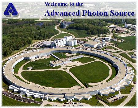

a) Left is a schematic of a synchrotron using acronyms defined in the text above and yellow for the path of x-ray beams. Typically a 3'rd generation synchrotron will have about 40 beams from BM's and ID's. Each beam is split into about 4 beamlines so about 200 different independent measurements are being made at one time. Often a beam line is shared by 2 to 4 instruments, only one of which is used at a time. b) In the photo of APS in Chicago (a third generation synchrotron) the ID is in the center of the ring, The RF is in the inner box attached to the ring, each outer triangle is for a collaborative access group (CAT) which generally runs 2 to 3 beams from the source which are split into beam lines. APS is one of the most advanced synchrotrons in the world. The third picture (top) is NSLS on Long Island near New York. NSLS is a second generation synchrotron that produces x-rays in the larger ring and UV radiation for micro-electronics processing and UV analysis in a smaller ring within the box building to the right. The two synchrotrons share ID's located between the two rings. In the fourth picture (bottom right) the interior of the Swiss Light Source (SLS) is shown during construction in 2002. The exterior of the SLS is composed of wood!
As a charged particle travels at the speed of light through a curved path a continuous spectrum of radiation is produced normal to the direction of change in momentum. The median wavelength, lc, is given by,
where R is the radius of curvature, E is the energy of the particle (typically GeV's), m is the mass of the particle and c is the speed of light. The term in brackets is typically 5.6 (GeV3)Ĺ/m [Roe, Methods of X-ray and Neutron Scattering in Polymer Science]. The angular divergence of an x-ray beam from an insertion device is typically a fraction of a milliradian and is calculated from [Roe],
Crystal Monochromators:
In addition to attenuation there are at least two other common means of isolating the K
a radiation. Some detectors, proportional counters, have the ability to discriminate energy of incoming radiation and to observe only a narrow window of the spectrum. This means of selecting the Ka radiation is usually used in addition to attenuation or crystal monochromatization since it is not completely discriminating.Bragg's law can be used to discriminate wavelengths through the use of a perfect crystal and collimation. We can write Bragg's law in terms of
l,l
= 2d sin(q)If
q is carefully controlled using slits and d is carefully controlled through the use of a perfect crystal, then a polychromatic source can be monochromatized. This is the best way of obtaining a single wavelength but since the intensity which comes out of a crystal diffraction event is small compared to the incident intensity, it has disadvantages. Usually a crystal monochromator is arranged in reflection to reduce the absorption of radiation by the diffracting material. A number of complex arrangements are possible which include curved or slightly bent crystals for focusing optics to improve collimation.Decay of EM radiation with distance
For an isotropic source such as the anode of an x-ray tube, the total intensity emitted decays by absorption as a function of distance according to Beers' Law. In addition to this effect, the Intensity decays by 1/r2
due to the isotropic nature of the radiation. Intensity is measured by a detector with a certain surface area exposed to the radiation. Thus, one always measures intensity in terms of I/Area. If the total integrated intensity is fixed, then the intensity per area is reduced as one moves from a source a distance r by the surface area of a sphere of radius r. This surface area is proportional to r2, so the Intensity per area decreases by 1/r2.Detectors
We will discuss detectors in some detail in later classes. An overview is given here for reference.
The simplest detector is a photographic film which contains x-ray absorbing material (Silver halide) which initiates a chemical reaction. The absorption coefficient of the film is important as are the kinetics of the reaction.
Scintillation Counters usually made by Bicron (silver tube) use a fluorescent sheet which emits light on exposure to x-rays. A photo detector is then used to detect x-rays (usually a photomultiplier tube).
Gas Detectors: Low Voltage = Ionization Chamber; Intermediate Voltage = Proportional Counter; High Voltage = Geiger counter
1) Ionization Chamber Energy Resolution, Low signal, Low voltage (200V). Current is proportional to number of photons.
2) Proportional counters use the ionization of a gas mixture by x-rays to produce a current or charge on a wire which is measured by electronics. These detectors can be tuned to detect only a certain range of photon energies. Voltage or current is proportional to number of photons. (1000V)
3) Geiger counters also use ionization of a gas but are not sensitive to the energy of the photons, i.e. they count all photons. Loose a direct proportionality between number of photons and detected intensity but this detector is very sensitive to low levels of radiation. Good for survey detector. (2000V).
Solid state detectors exist, CCD via fluorescence or directly or semi-conductor detectors.
Fluorescent screen detectors have a removable screen which is inserted into a screen reader after exposure.