Newtonian Isothermal Model for the Blown Film Process
![]()
The purpose of this section is to describe the blown film process, explain its inherent benefits to film properties, and model the effects of operating conditions, polymer characteristics, and equipment design on the final properties of the film. Such a model must incorporate the effects of the heat transfer between the film and the surrounding air to the rheological properties and crystallization dynamics of the molten polymer.
Blown film is a commercial process used to produce a number of products, including grocery bags, garbage bags, and food packaging. The following is an image of a typical blown film line:
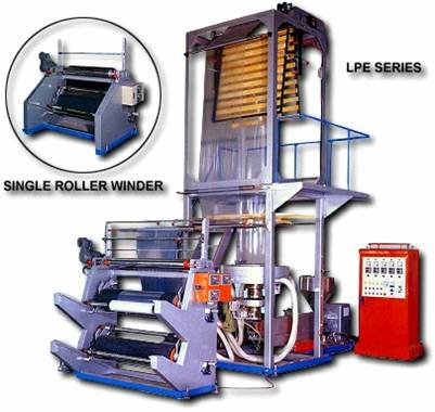

Images: www.lung-meng.com and www.plasticstechnology.com
Film construction can be as simple as a single extruder, monolayer film to a complex multilayer film consisting of a wide range of polymers. For example, a film used in a high barrier application could consist of up to nine individual layers of multiple polymers providing sealing, moisture and oxygen barrier, interlayer adhesion, and regrind. In some applications where a balance of machine and transverse direction properties is necessary, the blown film outperforms other fabrication processes, such as cast film.
In the blown film process, a polymer is extruded through an annular die and exits as a thin wall molten tube. The tube, or commonly know as the “bubble”, is inflated by internal air that is supplied through the inner mandrel of the die. Air is also blown on the external side of the bubble, via an air ring, which crystallizes the film. This crystallization process is evident by the presence of a frost line, or a ring around the bubble that typically appears hazier than the melt exiting the die. After crystallization, the film is collapsed between two rollers that set the take up rate of film. The film is then wound at tubing or may then be slit into sheeting and wound on separate rolls.
Operating conditions:
The uniqueness of the blown film process is the ability to balance the orientation between the machine and transverse direction. To do so, the blow up ratio and the draw down ratio are utilized.
The amount of air supplied to the inside of the bubble is directly related to the amount the film is “blown up”, and as a result, oriented in the transverse direction and is characterized the blow up ratio (BUR). The blow up ratio is simply the ratio of the final diameter of the tube relative to the die diameter.
![]()
The amount the film is oriented in the machine direction is controlled by the draw down ratio (DDR), which is simply the ratio of the thickness of the extrudate exiting the die to the final film gauge. For practical purposes, the thickness of the extrudate exiting the die is equivalent to the die gap opening.
![]()
A third ratio that incorporates the strain rate associated with the film blowing process is the machine-direction draw ratio (MDDR), which is the ratio of the take up speed relative to the extrudate speed at the die.
![]()
Equipment design and polymer rheology also plays a significant role in the properties of the film. For example, by utilizing low draw down ratios, high blow up ratios, polymers with longer relaxation times, and narrow die gaps, film with isotropic properties can be produced. In contrast, high draw down ratios, low blow up ratios, polymers with shorter relaxation times, and larger die gaps produce films with uniaxial orientation.
Newtonian, Isothermal Process
The model that will be presented, as described by Middleman [1], will represent a newtonian isothermal model with the intent of providing a simplified and practical vision into the relationship between polymer characteristics, operating conditions, and equipment design. A more accurate (and significantly more computationally complicated) model would account for non-isothermal [2,3]and viscoelastic conditions [4,5] that are evident in the realistic blown film process.
Figure 1-3 show various schematics of the blown film process.
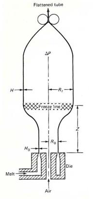
image: Middleman, S., Fundamentals of Polymer Processing, 1st edition, McGraw-Hill, 1977.
Figure 1 depicts the entire blown film tube, from die to take off nip. Noted are the initial film thickness (H0) =of the melt as it exits the die (or die opening), the pre-blown tube radius (R0), the frost line height (Z), the film thickness after blow up (H), the tube radius after blow up (Rf), and the pressure differential between the inside of the bubble and the ambient surroundings (DP).
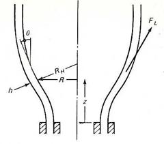
image: Middleman, S., Fundamentals of Polymer Processing, 1st edition, McGraw-Hill, 1977.
Figure 2 focuses on the dynamic zone of the blown film process, where the film begins to be blown in the transverse direction. Noted in the figure are the film thickness (h), the principal radius of curvature (RH), the radius to the inner wall of the film (R), the force in the longitudinal direction (FL), and the angle between the circumferential direction and the direction of flow (q), where the direction of flow is indicated by z.
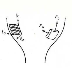
image: Middleman, S., Fundamentals of Polymer Processing, 1st edition, McGraw-Hill, 1977.
Figure 3 shows the dynamic coordinate system (noted by x1, x2, and x3) and the force in the longitudinal (FL) and circumferential (FH) directions. The noted cartesian system is embedded in an element of fluid in the inner surface of the film and moves with the film throughout the film blowing process.
Besides identifying the system as newtonian and isothermal, the model assumes:
|
The film is symmetrical about the z-axis | |
|
The film is thin with h/R<<1. This simplifies the velocity vector into only three nonvanishing components representing an elongational deformation field, eliminating the shear components. For this case, stresses are present in circumferential direction, direction of flow, and direction normal to the film surface. |
Referring to the moving system described in Figure 3, we note v as the velocity vector and e as the rate of deformation tensor, such that:

Direction normal to film
v2 is the velocity normal to the film thickness which is representative of the rate at which the film is thinning. Since h is a function of x1, and v1 (velocity in the machine direction) is defined by:
![]()
v2 can be defined by:
![]()
For a thin film, a good approximation for the gradient of velocity in the x2 direction (e22) (direction normal to the film surface) is simply the difference in velocity (v2) across the film thickness divided by the local film thickness:
![]()
Circumferential direction around the bubble
The rate at which the bubble expands, also known as the circumferential velocity, is:
![]()
Since symmetry is assumed about the z-axis, the bubble is expanding at a constant rate, and the stretching rate of deformation is the ratio of the increase of the circumference to the local value of the circumference.
![]()
Machine direction
By assuming the polymer is an incompressible fluid, the first invariant of the rate of deformation tensor vanishes so:

The following relationships transform the change in the machine direction elemental coordinate (x1) and the velocity in the machine direction (v1) to the coordinate laboratory system of the laboratory, where Q is the volumetric flow rate.
![]()
![]()
Substituting these relationships into the rate tensor equation results in:

Viscous stresses associated with the film blowing process
For a newtonian fluid, the viscous stress relative to direction ij is given by the following where p is the stress tensor in the xij coordinate system:
![]()
Since the elongational stresses acting on the film are in the machine (p11) and circumferential (p33) directions, and we assume no external stresses are acting on the film in the normal direction (p22=0), the following relationships are derived for the elongational and circumferential stresses by combining the viscous stress equation for a newtonian fluid and the rate tensor.
![]()
![]()
Relating the deformation field and the stress field into laboratory coordinates R(z) and h(z)
For a film with dimensions of 2pR by h by dx1, the longitudinal and circumferential forces can be calculated by:
![]()
![]()
Since the shape of the bubble is determined by the balance of forces on the film, the same methodology that is used to explain the interface subjected to surface tension (as described in Chapter 3 of Reference 1) is used to describe the pressure difference across the bubble surface (DP).

Where:
![]()

Balancing the forces applied to the film and relating
Next, we define the frost line height as Z, where dR/dz=0 such that the force draw force (Fz) is calculated from balancing the drawing force in the machine direction by the take up rollers and the blow up force resulting from the pressure differential between the inside of the bubble and the ambient conditions outside of the bubble.
![]()
In the above equation, Rf is the radius of the bubble at Z (frost line) and DP is the pressure inside the bubble relative to the external side of the bubble.
Relating changes in the radius of the tube (R) and film thickness (h) to position above the die (z)
By substituting the equations derived for p11, p33, RH, and RL into the equations for DP and Fz, two differential equations can be can be obtained that show the relationship between the radius of the tube (R) and the thickness of the film (h) with respect to position above the die (z).


Where:


![]()
Boundary Conditions of the Blown Film Process
To determine the film thickness and bubble radius at a given height from the die, the previously mentioned differential equations must be solved in series, with the first solved for R(z) and the second solved or h(z).
To solve the first equation, which is a second order differential equation, two boundary conditions must be set, which are:

For the second differential equation, only a single boundary condition is needed, which is:
![]()
If T, B, Z, and R0 are specified, the thickness reduction at x is given by: